53. Advanced turbine feature
The identification tag for this tutorial is PDS-ACG. Pregenerated input files for this tutorial are found in the folder named PDS-ACG in the provided tutorial input files.
53.1. Tutorial overview
This tutorial covers:
- Using turbine feature fluid velocity dependent thrust and torque coefficients
- Using thrust and torque coefficients dependent on both TSR and fluid velocity
- Using the transient response model to account for turbine acceleration
- Simulating turbine fault and transition cases
53.2. Creating the advanced turbine feature
- Make a copy of the project folder made for the ABA turbine feature tutorial. The copy will be modified for this tutorial.
- This tutorial will model a tidal turbine, so move the platform RigidBody platform to be 5 m below the sea surface.
Note
- The torque and thrust coefficients can be set to be dependent on either tip speed ratio (TSR), relative fluid velocity, or both.
- Example turbine data was created for this tutorial, the turbine data can be seen below. Please note that all turbine data provided in this tutorial was generated only for demonstrative purposes and does not represent the loading of a real turbine. Do not use this data in the place of real turbine data.
| U (m/s) | TSR | Thrust (N) | Torque (Nm) | Ct | Cq |
|---|---|---|---|---|---|
| 0 | 0 | 0 | 0 | 0.000 | 0.000 |
| 2 | 4 | 5000 | 1000 | 0.345 | 0.069 |
| 2.2 | 4.33 | 5200 | 2000 | 0.297 | 0.114 |
| 2.4 | 4.66 | 5400 | 3000 | 0.259 | 0.144 |
| 2.6 | 5 | 5600 | 4000 | 0.229 | 0.163 |
| 2.8 | 5.33 | 5800 | 5000 | 0.204 | 0.176 |
| 3 | 5.66 | 6000 | 6000 | 0.184 | 0.184 |
| 3.2 | 6 | 6200 | 7500 | 0.167 | 0.202 |
| 3.4 | 6.4 | 6400 | 8900 | 0.153 | 0.213 |
| 3.6 | 6.5 | 6600 | 8500 | 0.141 | 0.181 |
| 3.8 | 6.4 | 6800 | 8000 | 0.130 | 0.153 |
| 4 | 6.2 | 7000 | 7800 | 0.121 | 0.135 |
| 4.2 | 6 | 7200 | 7700 | 0.113 | 0.120 |
| 4.4 | 5.8 | 7400 | 7560 | 0.106 | 0.108 |
| 4.6 | 5.6 | 7600 | 7400 | 0.099 | 0.097 |
| 4.8 | 5.4 | 7800 | 7300 | 0.093 | 0.087 |
| 5 | 5.2 | 8000 | 7200 | 0.088 | 0.079 |
| 5.2 | 5 | 8200 | 7150 | 0.084 | 0.073 |
| 5.4 | 5 | 8400 | 7050 | 0.080 | 0.067 |
| 5.6 | 5 | 8600 | 6900 | 0.076 | 0.061 |
| 5.8 | 5 | 8800 | 6800 | 0.072 | 0.056 |
| 6 | 5 | 9000 | 6700 | 0.069 | 0.051 |
Note
- For this example, the TSR curve reduces at higher flow speeds. This could be caused by flexible turbine blades or active pitching to feather load in a real turbine system. Due to the fact that there are various flow speeds with the same TSR value, flow speed dependent thrust and torque coefficients must be used.
- To model this type of turbine, TSR dependent thrust and torque coefficients cannot be used. If TSR dependent coefficients were to be used then ProteusDS will have conflicting values. For example, using this data, there will be conflicting thrust and torque coefficients for flow speeds of 3 m/s and 4.6 m/s. Using TSR dependent coefficients will result potential errors when ProteusDS interpolates between these values.
- Create a new rigid body turbine feature and call it turbineAdvanced_3m.
- Input the turbine TSR curve using the
$PrescribedTSRproperty. Create a new property for each line entry. - Use the
$RelativeFluidVelocitiesproperty to set the flow speeds for the thrust and torque coefficient table. - Use the
$ThrustCoefficientproperty to set the thrust coefficients. Set the first value to 0, this value is used to set the TSR that corresponds to the thrust coefficients, however, we are not using TSR dependent values, therefore, set the value to 0. Following the first 0, set the thrust coefficients that correspond to the relative fluid velocities listed in the$RelativeFluidVelocitiesproperty. Only one$ThrustCoefficientline is required for this turbine. - Use the
$TorqueCoefficientproperty similarly to the$ThrustCoefficientproperty. - Set the turbine diameter to 3 m, the turbine swept area to 7.07 m2, the turbine axis to be the X axis, control parent RigidBody on.
- Ensure that
$Modeis set to 0.
Note
- The turbine properties should match those presented below. The torque and thrust coefficient lines are not complete due to space restrictions. Ensure that the table is complete with all the data provided.
// Configuration
$Mode 0
$ReferenceSweptArea 7.07
$ReferenceDiameter 3
$IsCrossFlowTurbine 0
$RotationAxis 0
$CutInSpeed 0
$CutOutSpeed 100

// Scheduling
$ScheduleMode 0

// Thrust and Torque Data
$RelativeFluidVelocities 0	2	2.2	2.4	2.6	2.8	3	3.2	3.4	3.6	3.8	4	4.2	4.4	4.6	4.8	5	5.2	5.4	5.6	5.8	6
$TorqueCoefficient 0	0	0.069010273	0.114066568	0.143771403	0.163337925	0.176046616	0.184027396	0.202178535	0.212522987	0.18104547	0.152931354	0.134570033	0.120494128	0.107792906	0.09653611	0.087460937	0.079499835	0.072991635	0.06673833	0.060736082	0.055799032	0.051374315
$ThrustCoefficient 0	0	0.345051367	0.296573076	0.258788525	0.228673095	0.204214074	0.184027396	0.167134256	0.152825519	0.140576483	0.129991651	0.120767978	0.112669834	0.105511575	0.099145194	0.093451412	0.08833315	0.083710687	0.079518011	0.075700045	0.072210512	0.069010273

$PrescribedTSR	0	4
$PrescribedTSR	2	4
$PrescribedTSR	2.2	4.33
$PrescribedTSR	2.4	4.66
$PrescribedTSR	2.6	5
$PrescribedTSR	2.8	5.33
$PrescribedTSR	3	5.66
$PrescribedTSR	3.2	6
$PrescribedTSR	3.4	6.4
$PrescribedTSR	3.6	6.5
$PrescribedTSR	3.8	6.4
$PrescribedTSR	4	6.2
$PrescribedTSR	4.2	6
$PrescribedTSR	4.4	5.8
$PrescribedTSR	4.6	5.6
$PrescribedTSR	4.8	5.4
$PrescribedTSR	5	5.2
$PrescribedTSR	5.2	5
$PrescribedTSR	5.4	5
$PrescribedTSR	5.6	5
$PrescribedTSR	5.8	5
$PrescribedTSR	6	5

// Transient Response Model
$TransientResponseModel 0
// $OperatingTransientResponseDampingRatio 1
// $OperatingTransientResponsePeriod 10
// $BrakingTransientResponseDampingRatio 1
// $BrakingTransientResponsePeriod 1
- Replace the old turbine feature with the new turbineAdvanced_3m feature in the rotor Rigidbody .ini file.
- Run the simulation multiple times in various currents, check the resulting angular velocity, TSR, thrust, and torque loads using the turbine feature turbineOutput.dat output file. The file will be located in the ResultsrotorturbineAdvanced3m folder.
Note
- It is important to note that the turbine feature updates the turbine’s angular velocity and thrust and torque loads based on the relative fluid velocity at the turbine hub at each time step. The response of the turbine to a changing fluid is instantaneous as the transient response model is turned off.
- Run the simulation with a 3 m/s current and 3 m 7 sec following waves and plot the axial relative fluid velocity (located in the axialRelVelHub.dat file) alongside the angular velocity of the turbine. The two follow the same trend without any lagging.
53.3. Simulate the turbine with transient response model
- To add the transient response model, change the property
$TransientResponseModelto 1 and resolve all follower properties.
Note
- The transient response model uses a 2nd order harmonic change model, or damped harmonic oscillator model.
- The properties used to define the change model are damping ratio and response period. The model can also be defined using rise time and overshoot by setting
$TransientResponseModel 2.
- Set the property
$OperatingTransientResponsePeriodto 10. - Leave the rest of the properties as their default values.
- Rerun the simulation in waves. Plot the angular velocity of the turbine alongside the axial relative fluid velocity at the hub.
Note
- The plot can be seen below for the turbine in 3 m/s steady current with 3 m, 7 sec following waves.
- Note that the turbine response is now delayed due to the transient response model.
- The transient response model will affect the angular velocity of the turbine. However, it is important to understand that the thrust and torque coefficients are still dependent only on relative fluid velocity and therefore the thrust and torque loads on the turbine have not changed due to the presence of the turbine.
- In order for the thrust and torque of the turbine to be properly modeled while using the transient response model, thrust and torque coefficients that are dependent on both relative fluid velocity and TSR must be provided.
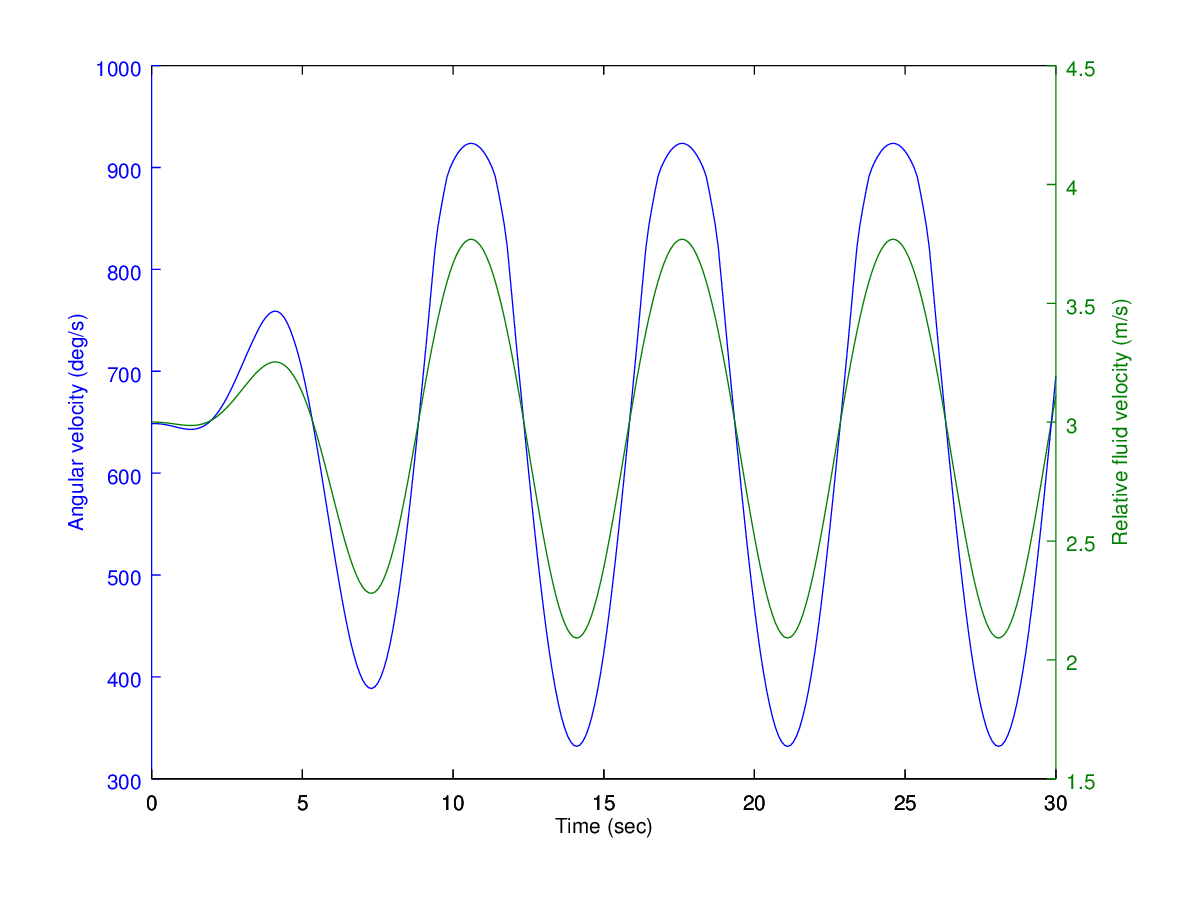
Fig. 53.1 Turbine angular velocity with no response model
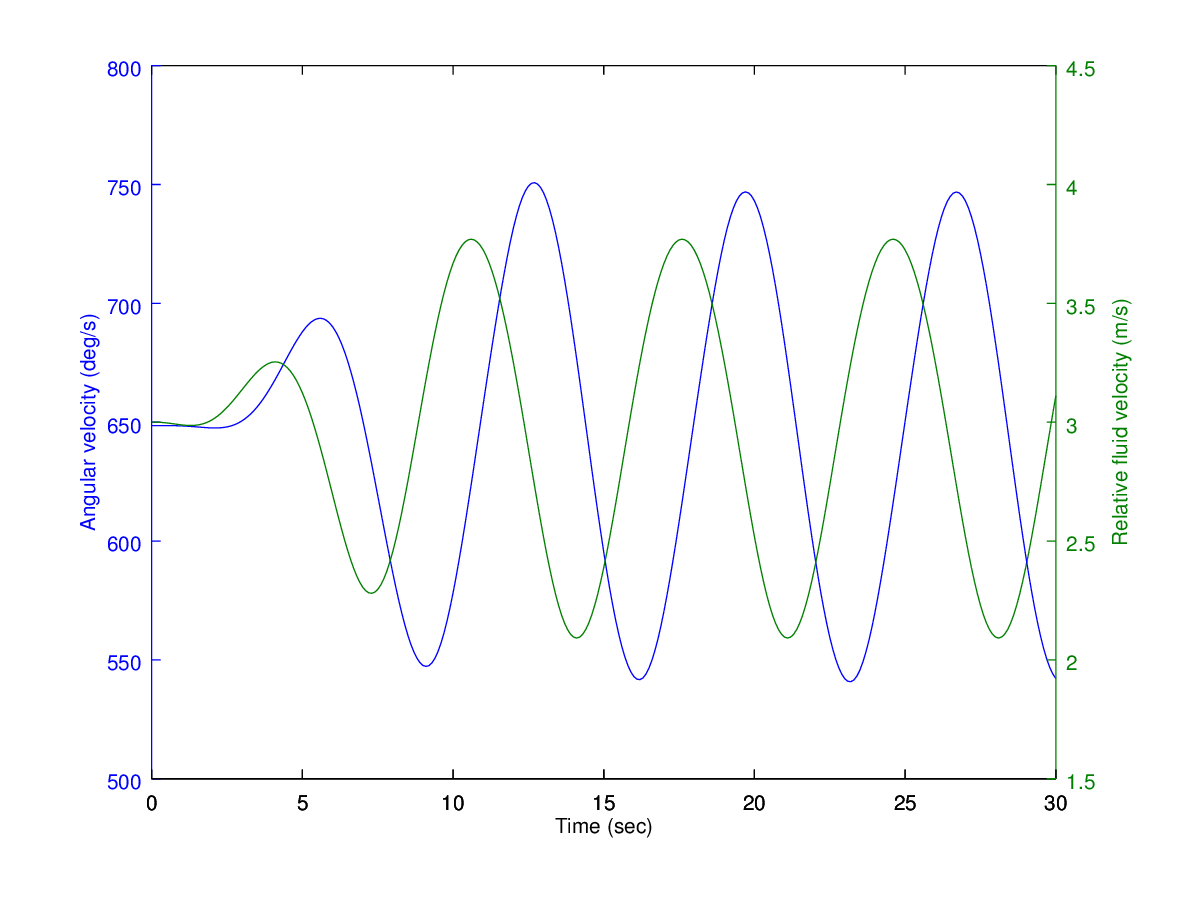
Fig. 53.2 Turbine angular velocity with response model
53.4. Using fluid velocity and TSR dependent coefficients
Note
- The tables below demonstrate thrust and torque coefficient data dependent on both fluid velocity and TSR.
| U (m/s) | 2 | 3 | 4 | 5 | 6 |
|---|---|---|---|---|---|
| TSR | |||||
| 0 | 0.140 | 0.140 | 0.140 | 0.140 | 0.140 |
| 4 | 0.638 | 0.575 | 0.495 | 0.401 | 0.296 |
| 4.5 | 0.634 | 0.560 | 0.467 | 0.358 | 0.234 |
| 5 | 0.624 | 0.539 | 0.432 | 0.304 | 0.160 |
| 5.5 | 0.617 | 0.522 | 0.404 | 0.263 | 0.104 |
| 6 | 0.607 | 0.502 | 0.373 | 0.218 | 0.042 |
| 6.5 | 0.594 | 0.481 | 0.339 | 0.167 | 0.000 |
| U (m/s) | 2 | 3 | 4 | 5 | 6 |
|---|---|---|---|---|---|
| TSR | |||||
| 0 | 0.050 | 0.050 | 0.050 | 0.050 | 0.050 |
| 4 | 0.068 | 0.069 | 0.072 | 0.076 | 0.079 |
| 4.5 | 0.110 | 0.111 | 0.113 | 0.115 | 0.115 |
| 5 | 0.128 | 0.127 | 0.125 | 0.124 | 0.121 |
| 5.5 | 0.121 | 0.119 | 0.117 | 0.114 | 0.110 |
| 6 | 0.110 | 0.108 | 0.105 | 0.100 | 0.095 |
| 6.5 | 0.096 | 0.093 | 0.089 | 0.084 | 0.077 |
- Create a new turbine feature turbineAdvanced2_3m and copy all the data from turbineAdvanced_3m.
- Update the
$RelativeFluidVelocitiesproperty with the new fluid velocity data. This is the data across the top of the table. - Update the
$ThrustCoefficientand$TorqueCoefficientproperties with the new data. The first column will be the TSR and the following columns will contain the coefficient data that corresponds to the correct TSR and fluid velocity.
Note
- The tables can be seen below:
// Configuration
$Mode 0
$ReferenceSweptArea 7.07
$ReferenceDiameter 3
$IsCrossFlowTurbine 0
$RotationAxis 0
$CutInSpeed 0
$CutOutSpeed 100

// Scheduling
$ScheduleMode 0

// Thrust and Torque Data
$RelativeFluidVelocities 0 2 3 4 5 6
$TorqueCoefficient	0	0.050	0.050	0.050	0.050	0.050
$TorqueCoefficient	4	0.068	0.069	0.072	0.076	0.079
$TorqueCoefficient	4.5	0.110	0.111	0.113	0.115	0.115
$TorqueCoefficient	5	0.128	0.127	0.125	0.124	0.121
$TorqueCoefficient	5.5	0.121	0.119	0.117	0.114	0.110
$TorqueCoefficient	6	0.110	0.108	0.105	0.100	0.095
$TorqueCoefficient	6.5	0.096	0.093	0.089	0.084	0.077

$ThrustCoefficient	0	0.140	0.140	0.140	0.140	0.140
$ThrustCoefficient	4	0.638	0.575	0.495	0.401	0.296
$ThrustCoefficient	4.5	0.634	0.560	0.467	0.358	0.234
$ThrustCoefficient	5	0.624	0.539	0.432	0.304	0.160
$ThrustCoefficient	5.5	0.617	0.522	0.404	0.263	0.104
$ThrustCoefficient	6	0.607	0.502	0.373	0.218	0.042
$ThrustCoefficient	6.5	0.594	0.481	0.339	0.167	-0.026

$PrescribedTSR	0	4
$PrescribedTSR	2	4
$PrescribedTSR	2.2	4.33
$PrescribedTSR	2.4	4.66
$PrescribedTSR	2.6	5
$PrescribedTSR	2.8	5.33
$PrescribedTSR	3	5.66
$PrescribedTSR	3.2	6
$PrescribedTSR	3.4	6.4
$PrescribedTSR	3.6	6.5
$PrescribedTSR	3.8	6.4
$PrescribedTSR	4	6.2
$PrescribedTSR	4.2	6
$PrescribedTSR	4.4	5.8
$PrescribedTSR	4.6	5.6
$PrescribedTSR	4.8	5.4
$PrescribedTSR	5	5.2
$PrescribedTSR	5.2	5
$PrescribedTSR	5.4	5
$PrescribedTSR	5.6	5
$PrescribedTSR	5.8	5
$PrescribedTSR	6	5

// Transient Response Model
$TransientResponseModel 1
$OperatingTransientResponseDampingRatio 1
$OperatingTransientResponsePeriod 10
$BrakingTransientResponseDampingRatio 1
$BrakingTransientResponsePeriod 1
- Update the turbine feature in the rotor rigid body ini file.
- Rerun the simulation in waves and check the resulting thrust and torque loads. Ensure that the thrust and torque loads are as expected.
Note
- The transient response controller will control the angular velocity of the turbine (and therefore affect the TSR), however, the thrust and torque loads are still calculated instantaneously based on the relative fluid velocity at the hub.
- As the relative fluid velocity at the turbine hub changes due to the waves, the turbine tries to change the TSR to the optimal TSR as defined by the
$PrescribedTSRproperty. However, the turbine is limited in acceleration due to the controller and therefore as it accelerates towards the optimal TSR, the turbine feature coefficients are interpolated based on the table provided. - If the turbine will also be in very slowly changing flow, the response model is not required and coefficients can be provided based only on relative fluid velocity similar to the turbineAdvanced_3m feature.
53.5. Fault Cases
Note
- The turbine feature can represent specific fault cases, such as: Turbine cut in, cut out, freewheel, and shutdown.
- Set the
$CutInSpeedto 2 m/s and the$CutOutSpeedto 4 m/s. - Set the current to 6 m/s and set a current ramp duration to 60 seconds. Specify
$EnvironmentTransitionMode 1and resolving follower properties. Set$CurrentTransitionMode 1to ramp current conditions. Set the corresponding ramp duration to 10 seconds. Turn off all waves. Ensure the simulation runs for at least 60 seconds. - Run the simulation.
- Plot the angular velocity of the turbine throughout the simulation. Notice the turbine does not begin to rotate until 20 seconds into the simulation (corresponding to a fluid velocity of 2 m/s) and stops rotating after 40 seconds (corresponding to 4 m/s current).
Note
- When the relative fluid velocity at the hub of the turbine is below the cut in speed or above the cut out speed, the turbine will act as if a mechanical brake is applied. The turbine will have no angular velocity and the thrust and torque coefficients will use a TSR of 0.
- Note that if thrust and torque coefficients are only dependent on relative fluid velocity then the turbine feature will not be functioning as desired as the loads will not change when the brake is applied.
- The transition between braked mode and operating mode is governed by the
$BrakingTransientResponseDampingRatioand$BrakingTransientResponsePeriodproperties. - The turbine can also be switched into braking mode, operating mode, or freewheeling mode at any time in the simulation using the
$ScheduleModeproperty.
- Set the
$ScheduleMode 1, resolve all follower properties.
Note
$ScheduleModeallows the user to specify what mode to transition into and what simulation time the change occurs at.
- Set the
$Scheduleproperty to$Schedule 2 10. - Add another
$Scheduleproperty beneath the previous one, set the property to$Schedule 1 20. - Set the
$PrescribedTSRFWproperty to$PrescribedTSRFW 0 10.
Note
- The
$PrescribedTSRFWproperty sets the freewheeling TSR for different fluid velocities. For simplicity we will provide only one value so that the turbine will always freewheel with a TSR of 10.
- Set the
$CurrentSpeedto 3 and remove the current ramp. - Run the simulation and plot the turbine angular velocity.
Note
- Notice the turbine transitioning from operating (the default mode) to freewheel at 10 seconds and then to braked mode at 20 seconds.
- To start the turbine in the braked or freewheeling mode, add the
$Scheduleproperty with the trigger time as 0 seconds. - The transition to freewheeling mode is governed by the
$FreeWheelTransientResponseDampingRatioand$FreeWheelTransientResponsePeriodproperties.