Blog
Know your fin stabilizers: sizing fins for forward speed
In part 1, we gave a broad overview of many fin stabilizer equipment suppliers available. While knowing what products are out there builds awareness, we still need to take tangible steps to understand the potential benefits of specific motion control equipment. This is especially helpful for setting realistic expectations and building a business case to inform refit or concept design decisions. In the context of fin stabilizers, the simplest first step is to work on a forward-speed application. In this article, we’re going to cover:
- fin area
- fin aspect ratio
- fin control gain
First, we’re going to go over fin area.
All performance scales with fin planform area
The planform area is what you see when you look down on the fin from above. For a rectangular fin, this will simply be the span multiplied by the chord. The area is so important because the larger the fin area, the greater the hydrodynamic forces. And the greater the hydrodynamic forces, the greater the motion control capacity there is.
Yet many other parameters beyond area affect the resulting fin stabilizer performance. So there’s no precise formula for fin size based on a ship. Still, some ideas can give a starting point. And a starting point is all we need because ship motion prediction software can give feedback on what-if scenarios about how much of an improvement there may be with a specific set of fins. Then we can adjust for bigger or smaller fins as needed, depending on the results. So what is a simple and crude rule to use as a starting point?
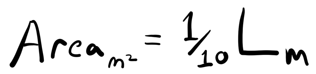
This crude rule of thumb shows the individual fin planform area in square meters is 1/10 the length of the ship in meters. For example, a monohull ship 100m long could use a pair of fin stabilizers, each with a fin area of 10 square meters. This rough rule of thumb is only a starting point and generally gives an idea for monohull ships in the 30m-100m range. The fin area will always vary around this factor depending on the ship’s needs and performance requirements, but it’s still a useful starting point. But knowing the planform fin area doesn’t quite let us define the fin dimensions. There’s another piece of information that’s needed, and that brings us to the second point on fin aspect ratio.
The aspect ratio shows the general shape of the fin
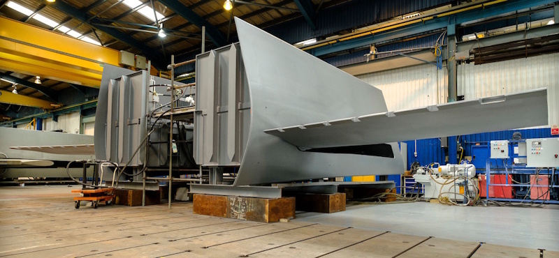
For a rectangular fin, the aspect ratio is the span divided by the chord. This is another crucial parameter which links to hydrodynamic performance. But the links are not always direct or obvious. In other words, a bigger aspect ratio doesn’t automatically mean better motion control performance. That said, higher aspect ratio (i.e. longer span) fins may generate greater resistance to roll at forward speed. On the other hand, lower aspect ratio (i.e. shorter span) fins tend to have an advantage in zero speed roll resistance.
No aspect ratio is the best all the time
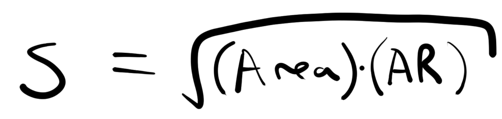
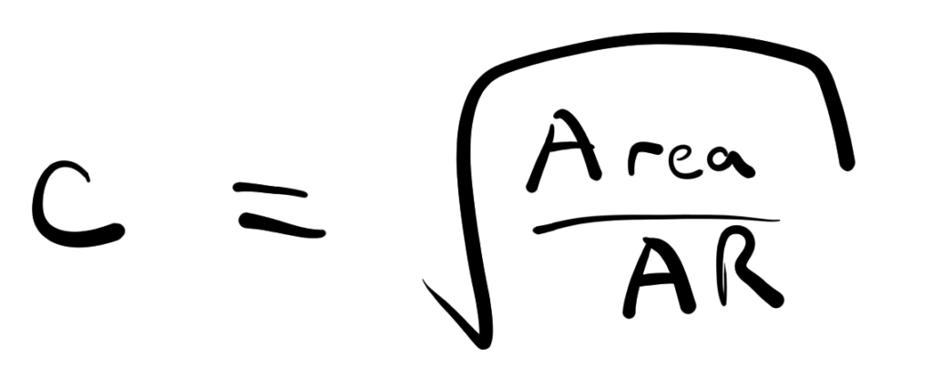
Nevertheless, it’s important to get the aspect ratio meaningfully close to the product you’re considering, so the behaviour is more likely to be representative. You can estimate this from pictures or from documentation from the equipment supplier, if available. Once you have an idea of fin aspect ratio and fin area, for a rectangular fin, the span and chord become clear:
With span and chord defined, forward speed fin stabilizers need one additional detail to establish motion-control performance. This brings us to the third and final point in this article on roll velocity control gain.
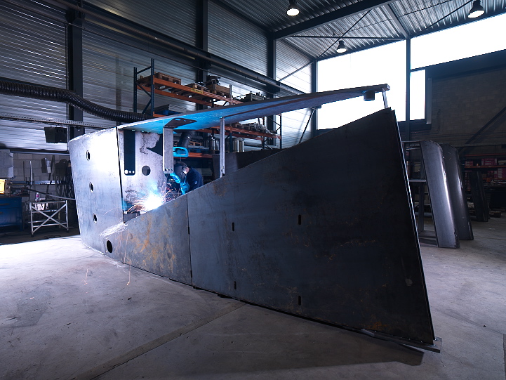
At forward speed, the fins actuate to resist roll motion
As the fins actuate, a hydrodynamic lift force develops on the fin, just as lift on airplanes develops in air. But in this case, this lift force resists the rolling direction of the ship. As the ship rolls back and forth, it also means the fins actuate in different directions to create that resistance.
The roll velocity control gain directly links the fin actuation angle with ship roll velocity. In other words, the faster the ship is rolling, the greater the actuation angle of the fin. This means the control action scales up with faster roll to keep things under control. For ship motion in a seaway, this means a roll velocity control gain works best to produce a damping response and slow things down. But what is a useful value for the gain coefficient?
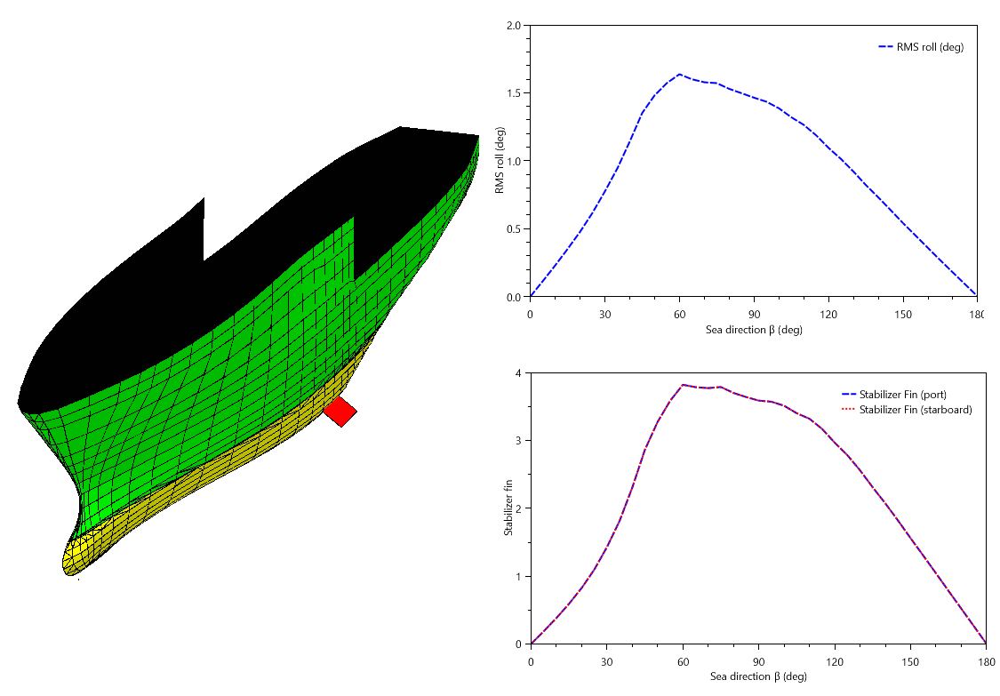
From experience, typical values seem to be in the range of 1-10 for ship motion parameters based on base-SI units. In the ProteusDS ShipMo3D toolset, the default value is -3 and is a typical starting point. Note that these coefficients are also signed: in other words, with the wrong sign, the fin system will exacerbate ship motion! In any case, you can use the control gain in conjunction with fin area to gauge both ship and fin motion performance. Much like airplanes, too much actuation and a steep angle of attack can lead to a stall condition, where the lift effect disappears entirely, along with all motion control capability. So when evaluating performance, keep an eye on fin RMS motions because they shouldn’t get too high in operational conditions. All else being equal, a larger fin area tends to reduce the required fin RMS motion and the chances of stall.
It’s summary time
We covered a few points on working with forward speed fin stabilizers, and now it’s time to summarize. Forward speed fins use hydrodynamic lift to resist roll motion at forward speeds. There will never be one perfect fin size for a ship, because a range of sizes may work fine. While a seakeeping analysis can give you confidence in what will work, you do need a starting point for fin parameters before you can begin. The first step is establishing a fin area. Many manufacturers have a rough guide for this, but several simple rules of thumb presented above can give you a starting point. Next, you need an aspect ratio, which you can determine from pictures or publicly available data. Once you have the fin area and aspect ratio, you can compute the span and chord for a rectangular fin. Finally, a forward speed fin actuation gain is needed, but a default value that can work well as a starting point in ProteusDS is listed above. Finally, when evaluating forward speed fin performance, be sure to keep an eye on RMS fin roll motion to avoid the possibility of stall in harsher conditions.
Thanks
Thank you to Kongsberg Maritime and Quantum Stabilizers for the helpful pictures of fin stabilizer equipment used in this article.
Next step
The next article in this series is on establishing parameters for zero speed fin capability. Read the article here. You can also watch a video tutorial that takes the ideas from this article and applies them in ProteusDS below.