


Blog
How zero speed fin stabilizers link power throughput to motion control
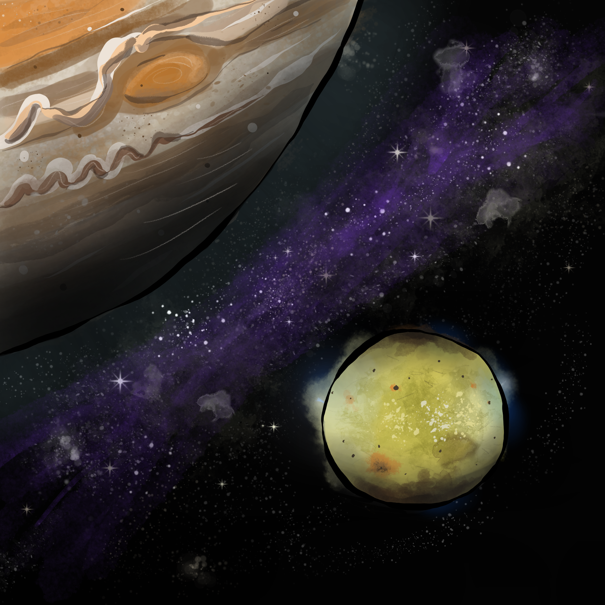
Volcanoes are not unique to Earth. On top of that, it turns out Earth is nowhere near the most volcanically active world in our solar system. Many are found on Io, a moon of Jupiter. Far from a geologically dead world, the surface of Io is in a state of constant change. All this change is caused by intense internal heating from Jupiter’s powerful gravitational field. However, Io is a fraction the size of Earth. And it has far fewer total volcanoes. Yet one supervolcano on Io is so active, it transmits more heat than all the volcanoes added up together on our own planet. So how can it be so much more volcanically active? It’s because it doesn’t matter how many volcanoes there are or how big they are. The reason is that volcanic activity depends on the amount of heat transmitted, or in other words, the power throughput.
This idea of power throughput is about transmitting energy from one form to another. And on Io, an enormous amount happens in a very small area. Likewise, in the world of ship motion control, an enormous amount of transmitting energy can happen in a small area. When it comes to fin stabilizer systems, power throughput can be absolutely crucial. This is particularly the case when it comes to fins operating in zero speed “paddling” mode. Zero speed motion control performance is closely tied to actuation power delivered through fin area: generally, the larger both of these are, the better the performance. But there are nuances to how fin area translates to the resistive hydrodynamic drag forces generated to slow ship roll. In this article, we’re going to talk about the mechanics of hydrodynamic power throughput of paddling fins. We’re going to talk about:
- fin aspect ratio and chord
- fin angle range
- fin area balance
First, we’re going to talk about fin aspect ratio and chord
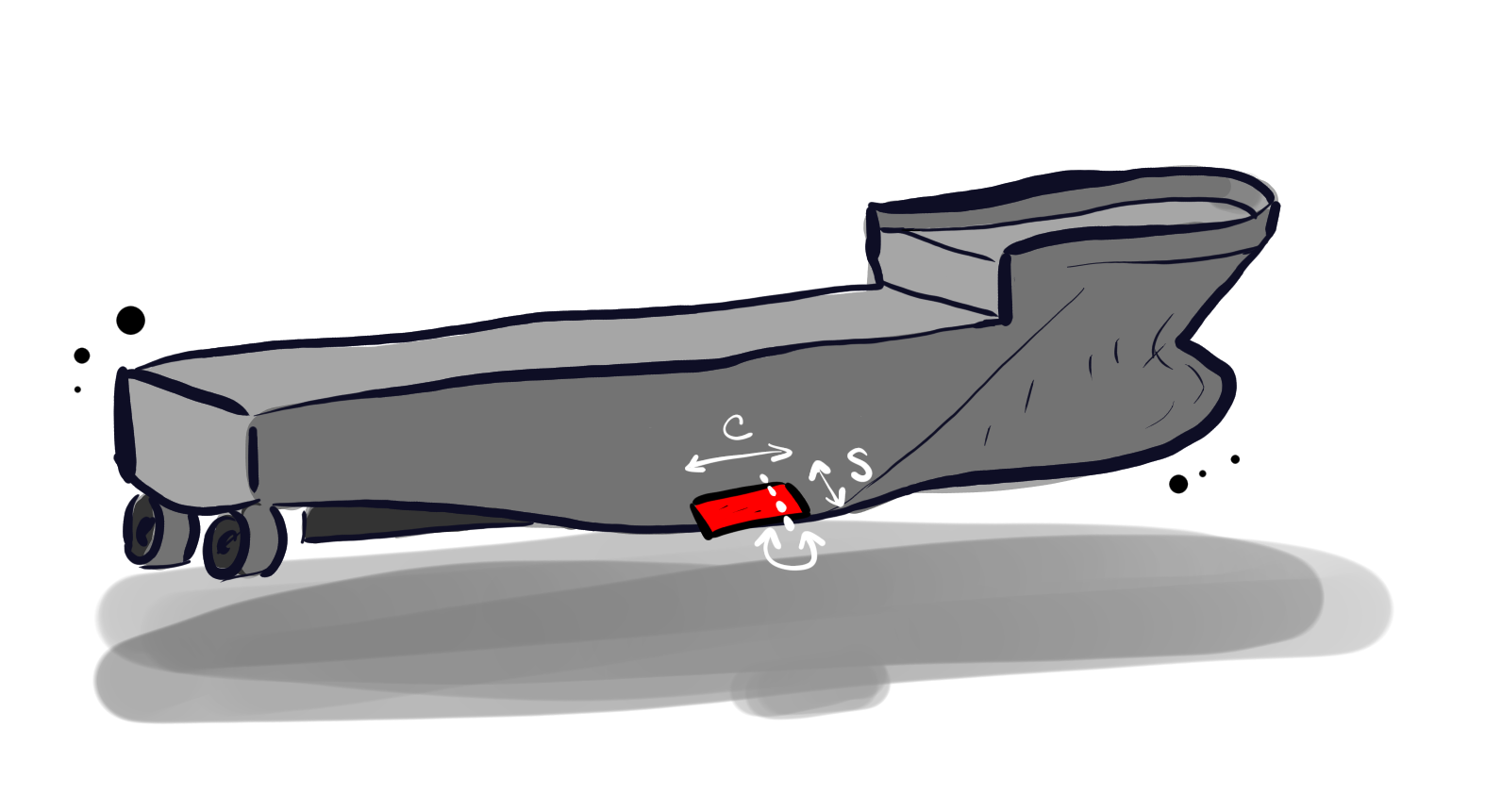
Aspect ratio is often simplified to span divided by chord. Many commercially available zero speed fins have a longer chord and shorter span, or in other words, a low aspect ratio. This is precisely because a longer chord produces more drag during paddling motion in zero speed conditions. And drag is what you want because it’s that drag that’s contributing to slowing roll motion. Yet that’s not to say that all zero speed fins must have a low aspect ratio: several models have much longer spans than their chords.
But why use short chord fins for zero speed?
If the zero speed damping improves with longer chord relative to span, it might seem that short chord zero speed fins might seem prohibitively inefficient. However, there are short chord zero speed fins available because of considerations that go beyond pure motion control capability. For example, zero speed capable fins with a short chord may be fully retractable, which then eliminates the risk of damage to the stabilizer system.
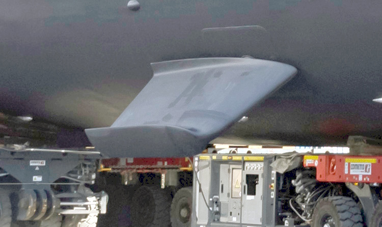
While fins with a high aspect ratio, or in other words, long span and short chord, might seem less efficient, there are other ways to compensate and create more roll-resisting hydrodynamic force at zero speed. This brings us to the second point on fin angle range.
The fin angle range defines the extent of paddling motion
The idea is the fin moves from one extreme angle to another. This requires significant mechanical power to generate hydrodynamic forces that resist roll motion. As a result, the fin usually quickly accelerates to a steady transit speed, when actuation power balances out with rotational drag. The greater the actuation power, the faster the transit speed and resulting paddling motion, allowing the fin to reach one end of its angle range to the other.
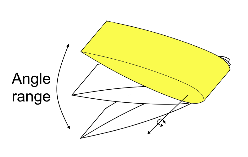
There’s no standard fin angle range: different fin products use different angle ranges. But generally, the greater the angle range, the more potential there is to create powerful hydrodynamic forces that slow down ship roll. While fin angle range provides a direct intuitive link to performance, there’s another parameter that helps you understand how much of the fin is helping overall. This brings us to the second point on fin balance.
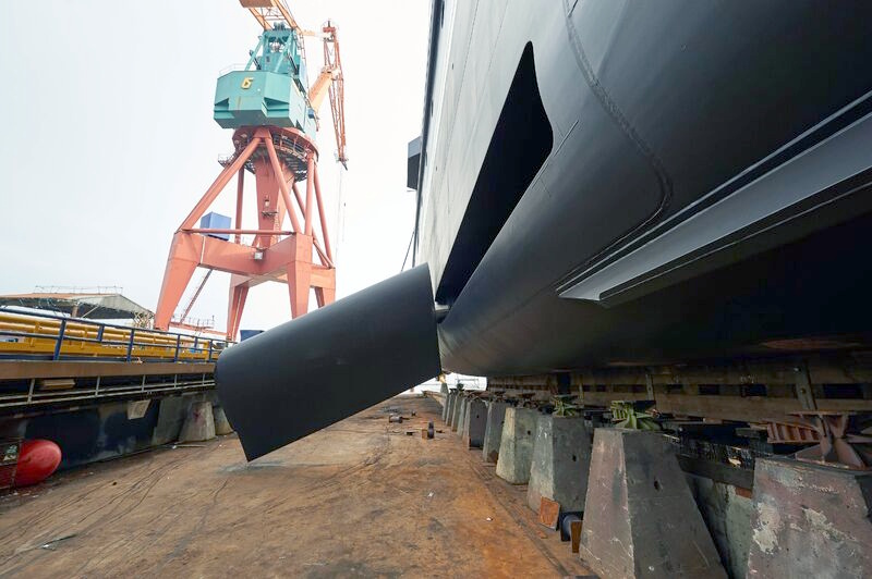
The balance of a fin is about how much area is in front of and behind the actuator axis
Typical ranges might be from 15% to 20% of the total fin area in front of the actuator. What’s critical about fin balance is that more area behind the actuator generates more roll-resistant drag in zero-speed mode. You might think it’s best to get a ‘zero balance’ fin design with all the area behind the actuator. It does help to get it as low as possible because the fin area ahead of the actuator works against zero speed stabilization performance. But it just isn’t structurally possible to get zero balance: there needs to be enough material surrounding the actuator to channel significant torque into the fin itself while operating.
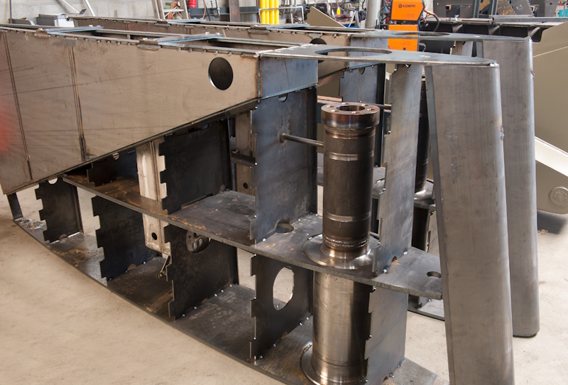
Another reason to avoid minimizing balance comes from how the fins operate at forward speed. In these conditions, the ship roll-controlling lift forces develop farther down the fin, meaning a very low balance fin has to exert a lot of actuator torque not only at zero speed but in forward speed mode, too. Excessive actuator torque during transit mode can increase wear on the system and potentially reduce performance at forward speed conditions. Nevertheless, fin balance is crucial for understanding zero speed performance.
Let’s look at an example
CMC Marine LR170
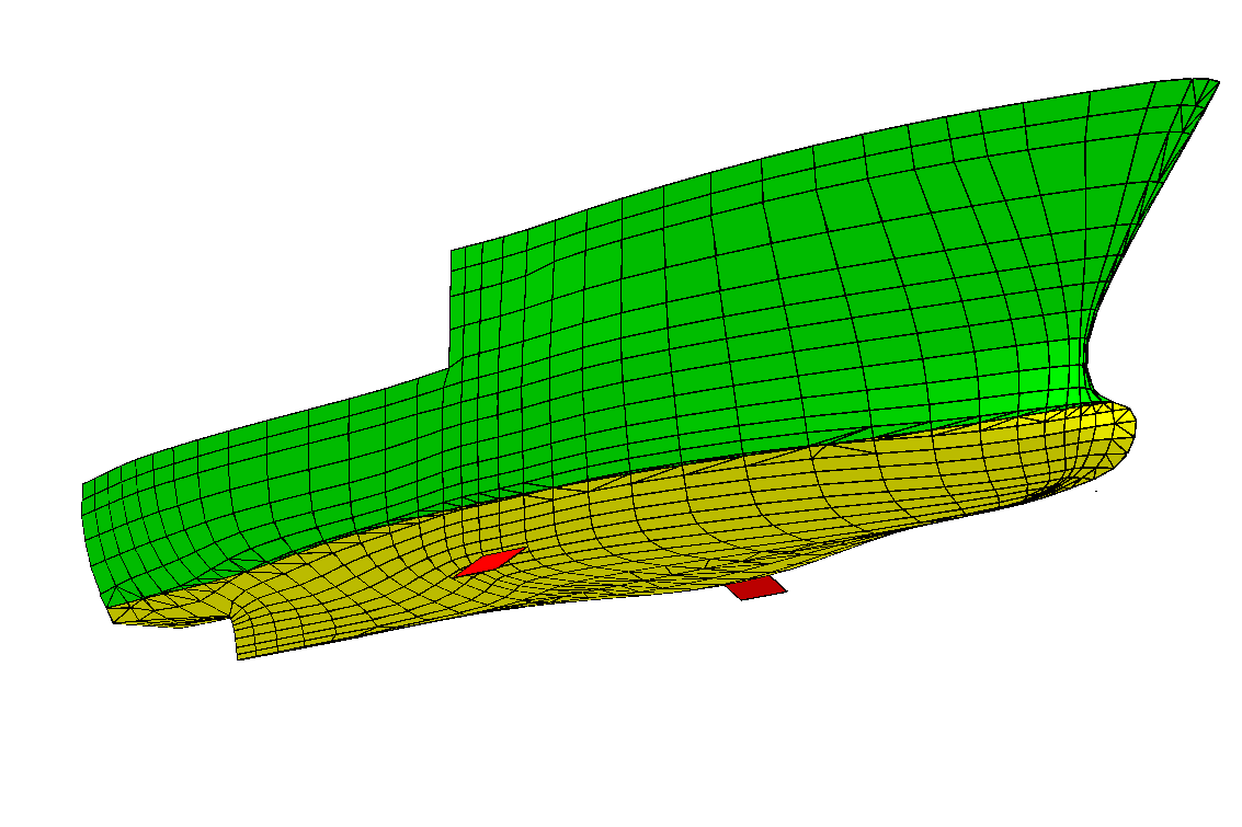
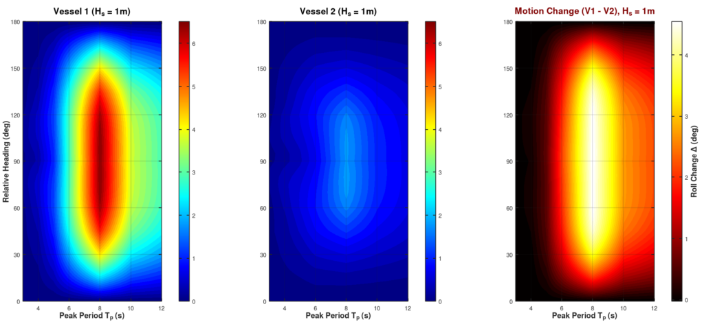
This shows the 50m Generic Yacht configured with 3.5m2 zero speed capable fins. These fins with an actuation power of 11 kW are a similar configuration possible with CMC Marine LR170 fins. So what kind of reduction in roll could a system like this produce? A quick comparison was completed using ProteusDS in a JONSWAP 1m, 8s sea state. In a worst-case beam sea condition, the RMS roll was 6.5 degrees bare hull, and 1.8 degrees stabilized, producing about 70% roll reduction. While this this is the best case scenario, roll motion is also improved across a range of other sea conditions. The figure below shows a heatmap of roll RMS motion with unstabilized (Vessel 1), stabilized (Vessel 2), and difference across a range of sea states and relative directions. The horizontal axis shows variation in sea state spectrum period, and vertical axis shows relative direction of the sea to the Generic Yacht (180 deg = head sea, 90 deg = beam sea).
It’s summary time
We covered a lot of detail on how fins work in zero speed mode, and it’s time to summarize. At zero speed, fins often rely on a paddling motion to damp ship roll. There are several ways the power throughput from the actuator translates into hydrodynamic roll damping. The first detail is fin aspect ratio: longer chord and shorter spans tend to create more resistance from this paddling motion. The second detail is the fin angle range, through which the fins will sweep in their paddling motion. The final detail is fin balance, or how much planform area lies in front of the actuator axis. Larger chord and sweep angle, and smaller balance, help improve zero speed damping performance. However, other considerations may also shape how equipment serves the ship it’s on. While there’s no perfect combination of parameters for a zero speed fin, each detail plays an important role in the resulting power throughput. Though small, these technologies pack a punch in a compact area – much like how the small moon of Io packs in the most volcanic activity in the solar system.
Thanks
Thank you to CMC Marine, SKF Marine, and Quantum Stabilizers for the very helpful pictures of fin stabilizer equipment used in this article.
Next Step
Several ProteusDS ShipMo3D toolset sample projects now come with zero speed fin configurations to explore. You can find the sample projects on the Documentation page here.
